(41) Test bench with a Wemos D1 mini and a 130*130 TFT display with SSD1283A controller
by Floris Wouterlood – July 8, 2020
Summary
This article describes the construction of a test bench whose main components are a Wemos D1 mini ESP8266 microprocessor board and a 1.6 inch 130*130 TFT display that is driven by a SSD1283A controller. The microprocessor board and the display are positioned on dedicate pin headers soldered onto a 60×80 mm print board. An additional 8-pin female pin header on the test bench supports sensor signal input, output and communication for devices being tested. Male pin headers on the bench supply 3.3V and 5V, and GND.
Introduction
Having a test bench at hand centered around a particular processor and display can be very effective. After constructing a modest series of dedicated test benches a welcome addition to the fleet is a bench around an ESP-8266 type microprocessor and a 130×130 transflective TFT display. Because of its minimal footprint and its versatility I like the Wemos D1 mini. Here the microprocessor chip is mounted on a 16-pin microboard that has full Arduino functionality plus wifi support, although at the expense of GPIO pins. As a SPI display such as the current one requires four GPIO pins, a total of eight pins of the Wemos remain accessible for sensors, output and communication. That is acceptable because most of my applications concern remote sensing of one or two environmental parameters.
Test benches are robust and reliable and once they are assembled one can focus on creating the software to optimize display behavior, to study library options, read sensors and construct external output and communication functionality.
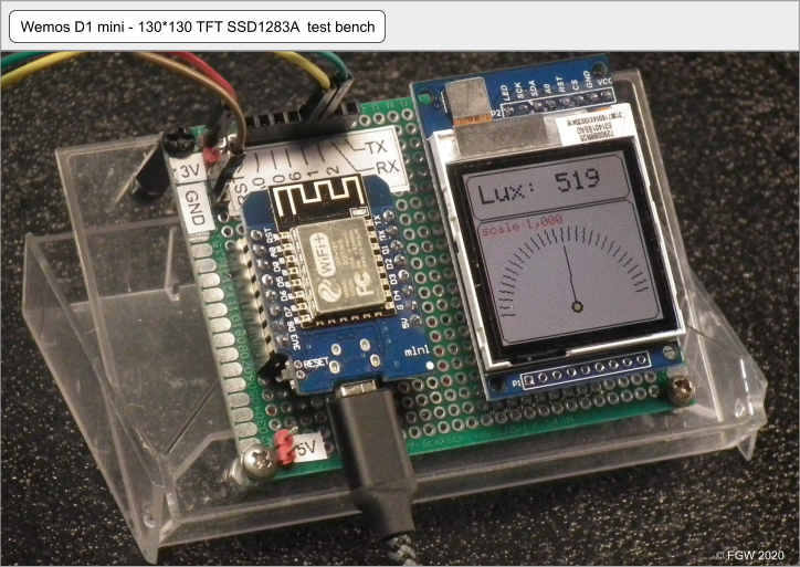
Figure 1: Wemos D1 mini 130*130 TFT test platform, completed and running the light intensity sensing demo. The two main components are placed on pin headers soldered onto a 60×80 mm double-sided universal PCB. The extra pin headers are connected to unoccupied pins of the Wemos. The PCB and its contents is conveniently mounted on an inverted cassette tape case. Bench pins D1 and D2 connect here to a BH1750 light sensor (i2c device).
The test platform (figure 1) contains a 130*130 transflective, 1.6-inch TFT display governed by a SSD1283A controller. Compared with OLED displays these TFTs have relatively large pixels. They require four wires (SCLK, MOSI, MISO and SS) (SPI interface). Remaining pins of the Wemos D1 are available for wired communication, sensors, leds and other external equipment. The SSD1283A TFT display supports graphical functions and 16-bit color instructions while individual pixels can be addressed. After assembly we will have added to the fleet an Arduino-compatible platform ready for testing a range of devices and sketches. My fleet will then consist of the bench under construction plus the following:
- Arduino Nano with a 16*2 or 20*4 LCD test bench*
- Arduino Nano with a 128*64 LCD test bench**
- Arduino Nano test bench with a socket that accepts various 240*320 and 320*480 TFT displays***
- Wemos D1 mini and 128*64 LCD test bench****
Required electronic parts
All the parts of the 130*130 Wemos D1 mini test bench are positioned on a 60×80 mm double-sided universal prototyping board (PCB) (schematic layout in figure 2).

Figure 2: Design of the test bench PCB with its main pin headers. Top left: layout with the two main components and the pin headers. Top right: wiring diagram for the TFT display and the test bench pin headers plus 3.3V, 5V and GND pins. Bottom left: wiring diagram for the test bench pin header. Bottom right: bottom view of the TFT wiring created to assist the soldering of the actual wires (quite helpful).
- 1x 60×80 mm double-sided universal Printed Circuit Board (PCB)
- 2x 8 pin female pin header: ‘Wemos D1 mini pin headers’
- 1x 8 pin female pin header: ‘TFT pin header’
- 1x 8 pin female pin header: ‘bench pin header’
- 1x 3 pin female pin header: serves as mechanical support for the TFT
- 1x 2 pin male pin header: 5V (red)
- 1x 2 pin male pin header: 3.3V (red)
- 1x 2 pin male pin header: GND (black)
- 2x nylon spacer with nylon bolt and nut
- 2x metal or nylon bolt and nut
- 1x Wemos D mini
- 1x 130*130 SSD1283A 1.6-inch diameter TFT display, SPI breakout board (8-pin)
wire - cassette tape case
Wiring and pin connectivity
A comprehensive wiring diagram that includes extra pin headers is presented in figure 2. The essential wiring (Wemos to TFT) is presented in the top right portion of that figure. This set of wires connects specific pins of the Wemos pin headers with their corresponding pins of the display pin header. Additional sets of wires connect the Wemos pin header and the test bench pin headers. These are shown in schematic in figure 2, bottom left. Finally, a set of wiring concerns the auxiliary 3.3V, 5v and GND power pins.
130*130 pixel 1283A TFT breakout board pin assignment table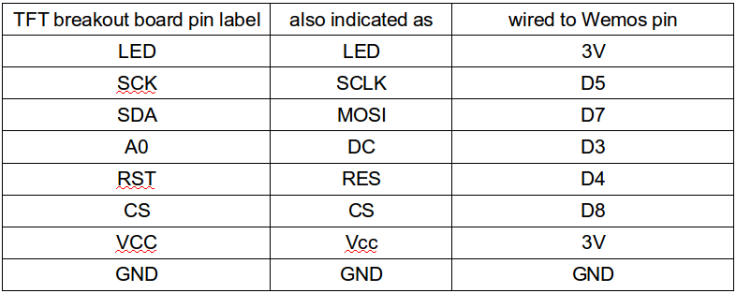
Test bench pins
The Table above indicates pins of the Wemos D1 that are ‘occupied’ by the display. This leaves the following pins available for applications: RST, A0, D0, D1, D2, D6, RX and TX. These Wemos pins are wired to the female eight-pin test bench header (visible in Figs. 1 and 3 at the top of the bench). This pin header is provided with a label on which the pin designations are printed.
External sensors and other devices need power and GND. To support this functionality I mounted 3V and 5V pins, as well as GND pins onto the PCB. Male pin headers were chosen intentionally for this purpose to physically separate the ‘power’ pin headers from the ‘sensor’ pin headers. Red signals ‘power’ while black signals ‘GND’. Labels are attached (figure 3).
Sketch
Here we present the ‘lux_meter_demo.ino’ sketch which consists of the core of a light intensity meter sketch published before*****. The light intensity sensor in that project was a BH1750 with i2c interface. The purpose of the sketch is show how well this combination of microprocessor board and TFT display performs. This particular TFT is transflective, i.e., it is designed to perform well under ambient light conditions.
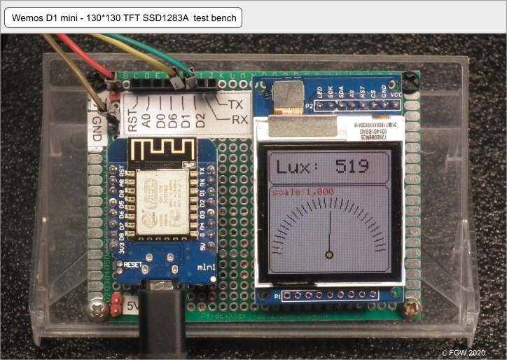
Figure 3: Top view of the completed test bench running the demo sketch. The wires coming from the bench pin connect a BH1750 light intensity sensor.
Discussion
After completion and check we have a fully workable and robust test bench (figure 3) ready to start working with: testing of external sensors and other devices as well as developing sketches. It is also an excellent platform to develop stop-motion animations such as Muybridge’s horse, ‘Sallie Gardner’.******
In order to protect the vulnerable bottom of the platform where all wires are located the platform is mounted with nylon spacers and screws onto the lid of an old cassette tape case. To get an angled position (see figure 1) the lid was taken off the case, turned around and replaced. Now we have a platform that is attractive and functional and that also enables proper and safe storage when not in use.
Sketch
Referred projects:
* Arduino LCD test bench
Floris Wouterlood – April 6, 2020
** Arduino 128*64 Liquid Crystal Display ST7920 test bench
Floris Wouterlood – May 8, 2020
*** Arduino analog test bench – Arduino test bench with a 3.5 inch TFT displaying in analog fashion
Floris Wouterlood – february 10, 2017
**** ESP8266 and ST7920 powered 128*64 Liquid Crystal Display in a test bench
Floris Wouterlood – June 9, 20020
***** Photometry displayed with a 130×130 pixel SSD1283A TFT screen and powered by an ESP8266 Wemos D1 mini
Floris Wouterlood – March 16, 2020
****** Stop-motion of Eadward Muybridge’s galloping horse on Arduino 128*64 LCD, OLED and various TFT displays
Floris Wouterlood – May 23, 2020
Sponsors
